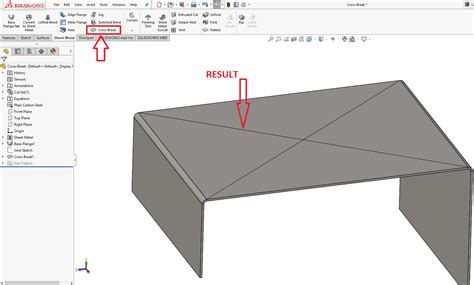
cross break sheet metal solidworks Use the Cross Break PropertyManager to add a graphical representation of a cross break to a sheet metal part. To display this PropertyManager: Click Cross Break (Sheet Metal toolbar), or .
For thin sheet metal welding it can be 30 ampere while for thicker (e.g. 1/8” square groove weld)- it can go up to 220 ampere for example. GMAW-S gives low heat and makes it easy to use in all positions on sheet metal, low carbon steel, low alloy steel, and stainless steel sheet metal from 25 gauge (0.02 inch or 0.5 mm) to 12 gauge (0.1 .
0 · sheet metal cross break tool
1 · sheet metal cross break
2 · SolidWorks sheet metal cross break
3 · SolidWorks cross break tool
4 · SolidWorks cross break template
5 · SolidWorks cross break layout
6 · SolidWorks cross break diagram
7 · SolidWorks cross break
The Fabricator is North America's leading magazine for the metal forming and fabricating industry. The magazine delivers the news, technical articles, and case histories that enable fabricators to do their jobs more efficiently.
The Cross Break command lets you insert a graphical representation of a cross break in a sheet metal part. The cross break is not a geometric entity and does not alter the geometry of the .Use the Cross Break PropertyManager to add a graphical representation of a .The Cross Break command lets you insert a graphical representation of a cross .Click Cross Break (Sheet Metal toolbar) or Insert > Sheet Metal > Cross Break. In .
A question we sometimes get in the SOLIDWORKS Sheet Metal course is how to insert a 3D cross-break. The functionality seems to be there in the SOLIDWORKS Cross .Use the Cross Break PropertyManager to add a graphical representation of a cross break to a sheet metal part. To display this PropertyManager: Click Cross Break (Sheet Metal toolbar), or .
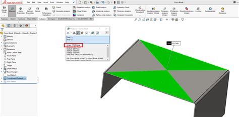
SolidWorks II Sheet Metal II Cross Break: A Cross Break in sheet metal is when multiple obtuse Bend Angles of approximately 170° are made across a flat secti.
The Cross Break command lets you insert a graphical representation of a cross break in a sheet metal part. The cross break is not a geometric entity and does not alter the geometry of the . Follow along using the transcript. 159 SolidWorks Sheet Metal Tutorial: Cross-Break, reasons to use, real examples, single and multiple faces, cross break options, editing cross-break.Click Cross Break (Sheet Metal toolbar) or Insert > Sheet Metal > Cross Break. In the PropertyManager, select: The face on which to create the cross break; The direction of the .Click Cross Break (Sheet Metal toolbar), or Insert > Sheet Metal > Cross Break. Face on which the cross break is inserted. Reverses the direction of the cross break in relation to the selected .
In HVAC or duct work design, cross breaks are used to stiffen sheet metal. The Cross Break command lets you insert a graphical representation of a cross break in a sheet metal part. The .Click Cross Break (Sheet Metal toolbar) or Insert > Sheet Metal > Cross Break. In the PropertyManager, select: The face on which to create the cross break; The direction of the .The Cross Break command lets you insert a graphical representation of a cross break in a sheet metal part. The cross break is not a geometric entity and does not alter the geometry of the part. You add it to provide the information needed to create the cross break during manufacturing. A question we sometimes get in the SOLIDWORKS Sheet Metal course is how to insert a 3D cross-break. The functionality seems to be there in the SOLIDWORKS Cross-Break command on the Sheet Metal toolbar, but upon inspection, the .
Use the Cross Break PropertyManager to add a graphical representation of a cross break to a sheet metal part. To display this PropertyManager: Click Cross Break (Sheet Metal toolbar), or Insert > Sheet Metal > Cross Break .
SolidWorks II Sheet Metal II Cross Break: A Cross Break in sheet metal is when multiple obtuse Bend Angles of approximately 170° are made across a flat secti.The Cross Break command lets you insert a graphical representation of a cross break in a sheet metal part. The cross break is not a geometric entity and does not alter the geometry of the part. You add it to provide the information needed to create the cross break during manufacturing. Follow along using the transcript. 159 SolidWorks Sheet Metal Tutorial: Cross-Break, reasons to use, real examples, single and multiple faces, cross break options, editing cross-break.Click Cross Break (Sheet Metal toolbar) or Insert > Sheet Metal > Cross Break. In the PropertyManager, select: The face on which to create the cross break; The direction of the cross break; The Break Radius; The Break Angle; Click .
Click Cross Break (Sheet Metal toolbar), or Insert > Sheet Metal > Cross Break. Face on which the cross break is inserted. Reverses the direction of the cross break in relation to the selected face. Click to edit the profile sketch of the cross break to move corners and change relationships.In HVAC or duct work design, cross breaks are used to stiffen sheet metal. The Cross Break command lets you insert a graphical representation of a cross break in a sheet metal part. The cross break is not a geometric entity and does not alter the geometry of the part.Click Cross Break (Sheet Metal toolbar) or Insert > Sheet Metal > Cross Break. In the PropertyManager, select: The face on which to create the cross break; The direction of the cross break; The Break Radius; The Break Angle; Click .The Cross Break command lets you insert a graphical representation of a cross break in a sheet metal part. The cross break is not a geometric entity and does not alter the geometry of the part. You add it to provide the information needed to create the cross break during manufacturing.
A question we sometimes get in the SOLIDWORKS Sheet Metal course is how to insert a 3D cross-break. The functionality seems to be there in the SOLIDWORKS Cross-Break command on the Sheet Metal toolbar, but upon inspection, the .Use the Cross Break PropertyManager to add a graphical representation of a cross break to a sheet metal part. To display this PropertyManager: Click Cross Break (Sheet Metal toolbar), or Insert > Sheet Metal > Cross Break .
SolidWorks II Sheet Metal II Cross Break: A Cross Break in sheet metal is when multiple obtuse Bend Angles of approximately 170° are made across a flat secti.
The Cross Break command lets you insert a graphical representation of a cross break in a sheet metal part. The cross break is not a geometric entity and does not alter the geometry of the part. You add it to provide the information needed to create the cross break during manufacturing.
Follow along using the transcript. 159 SolidWorks Sheet Metal Tutorial: Cross-Break, reasons to use, real examples, single and multiple faces, cross break options, editing cross-break.
Click Cross Break (Sheet Metal toolbar) or Insert > Sheet Metal > Cross Break. In the PropertyManager, select: The face on which to create the cross break; The direction of the cross break; The Break Radius; The Break Angle; Click .Click Cross Break (Sheet Metal toolbar), or Insert > Sheet Metal > Cross Break. Face on which the cross break is inserted. Reverses the direction of the cross break in relation to the selected face. Click to edit the profile sketch of the cross break to move corners and change relationships.
In HVAC or duct work design, cross breaks are used to stiffen sheet metal. The Cross Break command lets you insert a graphical representation of a cross break in a sheet metal part. The cross break is not a geometric entity and does not alter the geometry of the part.
1995 gmc 1500 fuse box mounting bracket

sheet metal cross break tool
sheet metal cross break

Still, it’s possible to weld thin sheet metal using the MIG (GMAW), TIG (GTAW), and stick (SMAW) processes. But MIG and TIG provide the best results. This article will teach you how to weld thin gauge metal using each arc welding process and present the common pitfalls beginners make.
cross break sheet metal solidworks|SolidWorks cross break diagram