bend a converted sheet metal parts in solidworks Click Insert Bends (Sheet Metal toolbar) or Insert > Sheet Metal > Bends.; In the PropertyManager, under Bend Parameters:. Click a face or edge on the model for Fixed Face . As there are a couple of options, my recommendation would be either an E6011 or E6013rod. Advantage of these electrodes are the high cellulose content in the coating, which . See more
0 · sketched bend in SolidWorks
1 · how to use sketched bend
2 · bend relief sheet metal SolidWorks
3 · SolidWorks sheet metal sketched bend
4 · SolidWorks sheet metal round bend
5 · SolidWorks sheet metal k factor
6 · SolidWorks sheet metal curved bend
7 · SolidWorks bend allowance table
Based on this information, I would say the box you want to use will support less than 10 lbs. The best options in your situation, would be to move the fixture location to allow you to fasten the box to a structural member, or add a structural member to mount the box to.
The Convert to Sheet Metal command lets you specify the thickness, bends, and rips necessary to convert a solid part to a sheet metal part.Click Insert Bends (Sheet Metal toolbar) or Insert > Sheet Metal > Bends.; In the PropertyManager, under Bend Parameters:. Click a face or edge on the model for Fixed Face . In this video we will show you some basics on how to convert a part that resembles something that can be made out of sheet met.Convert the part to sheet metal by clicking Insert Bends or Insert > Sheet Metal > Bends. If you want to make a cut across a bend, drag the rollback bar before the Process-Bends feature in .
Converting a Solid Part to a Sheet Metal Part. The Convert to Sheet Metal command lets you specify the thickness, bends, and rips necessary to convert a solid part to a sheet metal part. .Insert Bends or “Convert to Sheet Metal” features. When designing with sheet metal, it is important to think about the best approach to model or design a part. At times, it may appear .
In this tutorial, learn the difference between SOLIDWORKS Sheet Metal bend calculations including k-factor, bend allowance, and bend deduction with examples.Sharp bends, round bends, and flat bends are the three types of bends that may be applied when converting a solid body to a sheet metal part using the Insert Bends or Convert to Sheet Metal .

Convert to Sheet Metal: Once the solid model is complete, use the “Convert to Sheet Metal” tool to convert the model into a sheet metal part. This tool allows you to select a fixed face as the base, specify the material . Below are a few modelling techniques for Sheet Metal parts. 1. BENDING LINES TO THE VISIBLE CONVERSION CONE. Cone-shaped Sheet Metal parts are traditionally always modelled in SolidWorks using the ‘Lofted .The Convert to Sheet Metal command lets you specify the thickness, bends, and rips necessary to convert a solid part to a sheet metal part.
Click Insert Bends (Sheet Metal toolbar) or Insert > Sheet Metal > Bends.; In the PropertyManager, under Bend Parameters:. Click a face or edge on the model for Fixed Face or Edge.The fixed face remains in place when the part is flattened. Set a value for Bend Radius.; Under Bend Allowance, select from: Bend Table, K-Factor, Bend Allowance, Bend Deduction, .In this video we will show you some basics on how to convert a part that resembles something that can be made out of sheet met.Convert the part to sheet metal by clicking Insert Bends or Insert > Sheet Metal > Bends. If you want to make a cut across a bend, drag the rollback bar before the Process-Bends feature in the FeatureManager design tree.
Converting a Solid Part to a Sheet Metal Part. The Convert to Sheet Metal command lets you specify the thickness, bends, and rips necessary to convert a solid part to a sheet metal part. Converting an Imported Part to a Sheet Metal Part. You can convert any imported sheet metal type part to a SOLIDWORKS sheet metal part.Insert Bends or “Convert to Sheet Metal” features. When designing with sheet metal, it is important to think about the best approach to model or design a part. At times, it may appear quicker to use non-sheet metal features (boss-extrude, etc.), .

In this tutorial, learn the difference between SOLIDWORKS Sheet Metal bend calculations including k-factor, bend allowance, and bend deduction with examples.
Sharp bends, round bends, and flat bends are the three types of bends that may be applied when converting a solid body to a sheet metal part using the Insert Bends or Convert to Sheet Metal tools. Convert to Sheet Metal: Once the solid model is complete, use the “Convert to Sheet Metal” tool to convert the model into a sheet metal part. This tool allows you to select a fixed face as the base, specify the material thickness, and define the bends. Below are a few modelling techniques for Sheet Metal parts. 1. BENDING LINES TO THE VISIBLE CONVERSION CONE. Cone-shaped Sheet Metal parts are traditionally always modelled in SolidWorks using the ‘Lofted Bends’ feature.
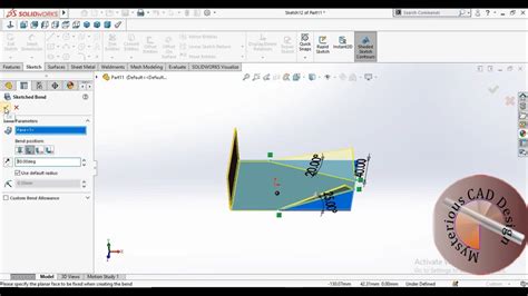
sketched bend in SolidWorks
The Convert to Sheet Metal command lets you specify the thickness, bends, and rips necessary to convert a solid part to a sheet metal part.
Click Insert Bends (Sheet Metal toolbar) or Insert > Sheet Metal > Bends.; In the PropertyManager, under Bend Parameters:. Click a face or edge on the model for Fixed Face or Edge.The fixed face remains in place when the part is flattened. Set a value for Bend Radius.; Under Bend Allowance, select from: Bend Table, K-Factor, Bend Allowance, Bend Deduction, .In this video we will show you some basics on how to convert a part that resembles something that can be made out of sheet met.Convert the part to sheet metal by clicking Insert Bends or Insert > Sheet Metal > Bends. If you want to make a cut across a bend, drag the rollback bar before the Process-Bends feature in the FeatureManager design tree.
Converting a Solid Part to a Sheet Metal Part. The Convert to Sheet Metal command lets you specify the thickness, bends, and rips necessary to convert a solid part to a sheet metal part. Converting an Imported Part to a Sheet Metal Part. You can convert any imported sheet metal type part to a SOLIDWORKS sheet metal part.
Insert Bends or “Convert to Sheet Metal” features. When designing with sheet metal, it is important to think about the best approach to model or design a part. At times, it may appear quicker to use non-sheet metal features (boss-extrude, etc.), . In this tutorial, learn the difference between SOLIDWORKS Sheet Metal bend calculations including k-factor, bend allowance, and bend deduction with examples.Sharp bends, round bends, and flat bends are the three types of bends that may be applied when converting a solid body to a sheet metal part using the Insert Bends or Convert to Sheet Metal tools. Convert to Sheet Metal: Once the solid model is complete, use the “Convert to Sheet Metal” tool to convert the model into a sheet metal part. This tool allows you to select a fixed face as the base, specify the material thickness, and define the bends.
how to use sketched bend

In this Instructable I'm going to walk you through how to make one of these simple sheet metal boxes! If you are just beginning to work with sheet metal I recommend also checking out my .
bend a converted sheet metal parts in solidworks|SolidWorks sheet metal curved bend